How to Orient a Model for the Strongest Print
Orient the model so the layer lines run along the load, not across it. An FDM part is a stack of welded plastic ribbons, and the weld between two layers is always the weakest thing in the part, so the strongest orientation is whichever one keeps force travelling inside a layer instead of trying to peel one layer off the next. Everything else about orientation — support material, surface finish, print time, price — follows from that single decision, which is why it is worth making deliberately instead of accepting whatever pose your model happened to be exported in.
Why Layer Direction Decides Strength
A 0.4 mm nozzle lays a bead of molten plastic beside the bead next to it and on top of the layer beneath it. Within a layer, those beads are extruded hot and squashed together, so the material behaves close to bulk plastic. Between layers, the new bead lands on plastic that has already started to cool, and the bond depends on how much of that older surface it can re-melt. On a modern high-flow hotend that bond is genuinely good — nothing like the flaky joints of a decade ago — but it is still the first thing to give. Layer adhesion is always the weakest direction in a printed part, and that single fact is what turns orientation from a convenience into a strength decision.
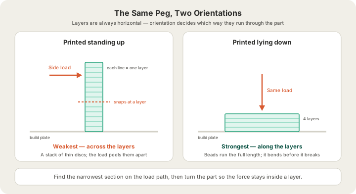
This is why the same geometry can behave like two different parts. A 6 mm peg printed standing on the bed is a stack of thin discs; push it sideways and every bit of that force tries to shear one disc off another, and it snaps clean at a layer line. The identical peg printed lying down has its beads running end to end along its length, so the same sideways push bends it instead. Nothing changed but which way up it went on the plate.
Find the Load Path First
Before you touch a rotate tool, work out where force enters the part, where it leaves, and what the thinnest cross-section on that route is. That is the load path, and it is the only thing orientation has to serve.
- Where does the load come in? A screw head, a hook, a hand, the weight of whatever sits on the shelf.
- Where does it go out? Almost always a mounting face, a bolt hole, or the ground.
- What is the narrowest section between those two points? That is where the part will break, and it is the one place layer direction genuinely decides the outcome.
- Which way do layers have to run through that section to keep the force inside them? Print that pose, and budget for the support it needs.
Most parts fail in one place, not everywhere, so you are optimising a single cross-section rather than the whole model. A phone stand that carries its load through a 4 mm elbow only cares about the elbow. Once you have found it, the rest of the orientation argument is about support, surface finish and time — real considerations, but negotiable ones.
Orientation by Part Type
| Part | Print it | Because | Watch for |
|---|---|---|---|
| Hook or J-bracket | Lying flat, its plane on the bed | The tension path stays inside one layer all the way round the curve | Big flat faces can lift at a corner; a brim fixes it |
| Cantilever snap-fit clip | Flat, beam running along the bed | The clip flexes along the beads instead of peeling layers apart | Add a fillet at the root or it cracks there anyway |
| Threaded post or pin | Lying down; split it if it is long | A standing pin shears at a layer under any side load | Threads come out rougher on the downward-facing side |
| Ring, tube or bushing | Standing, axis vertical | Hoop stress runs around inside a layer, and the bore stays round | The bore needs no support, but the outside profile might |
| Box or enclosure | Open face up | Walls carry load along their layers and need nothing inside them | A flat lid has to bridge; chamfer the top edge instead |
| Figurine or display piece | Whatever leaves the least support on a face you will look at | Nothing is load-bearing, so surface finish wins outright | Support scars land exactly where the support touched |
Two of those rows are really tolerance decisions wearing an orientation costume. A hole printed with its axis vertical comes out rounder than the same hole printed horizontally, which sags into a slight oval as it bridges its own ceiling. We go into that, and the clearances that make printed parts actually fit together, in /blog/3d-printing-tolerances-guide.
What the Strong Orientation Costs
Here is the part nobody mentions: the strongest orientation is usually the expensive one. Turning a part so its load path runs along the layers tends to lift geometry off the bed, and anything hanging in the air at more than roughly 45 degrees from vertical needs scaffolding under it. That scaffolding is printed plastic. It is extruded, paid for, then snapped off and binned.
Take a 62 g L-bracket in PLA. Laid flat on its back it needs no support at all and slices at 62 g — but the layers run straight across the corner where it will break. Tipped up so the load path follows the beads, the underside of the arm now needs support, and the same part slices closer to 88 g. At our $0.12 per gram all-in PLA rate that is $7.44 against $10.56, and because the quote comes from a real OrcaSlicer slice of your file rather than a volume estimate, the support shows up in the number before you pay rather than as a surprise afterwards.
| Orientation | Support | Billable | PLA cost | Strength |
|---|---|---|---|---|
| Layers across the load | none | 62 g | $7.44 | Weakest |
| Tipped 45 degrees | 9 g | 71 g | $8.52 | Strong |
| Layers along the load | 26 g | 88 g | $10.56 | Strongest |
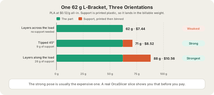
The middle row is where most real parts land. Tipping a model 20 to 45 degrees instead of standing it fully upright often recovers most of the strength for a third of the support, because the critical section is no longer square to the load even though the part is nowhere near vertical. It shortens the print too: Z height drives layer count, and layer count drives hours. /blog/how-long-does-3d-printing-take has the real numbers on what that does to a turnaround.
When No Orientation Works
Some parts have two load paths at right angles to each other and no single pose serves both. At that point orientation has run out of road, and you have four moves left.
- Add walls, not infill. Perimeters follow the outline of the part in every layer, so by definition they carry load in the strong direction. Going from two walls to four usually buys more real strength per gram than doubling the infill density — the arithmetic is in /blog/3d-printing-infill-explained.
- Split the part and join it. Two pieces, each printed in its own best orientation and bonded or bolted at a face that is not on the load path, beats one piece printed badly.
- Change material. PETG and ASA tolerate flex and impact far better than PLA at identical geometry; /blog/pla-vs-petg-vs-abs-vs-asa-vs-tpu compares all five we stock, including what each costs per gram.
- Redesign the corner. A great many orientation problems are really a stress concentration at a sharp internal corner. A 2 to 3 mm fillet there does more than any rotation will.
How the Farm Handles Orientation
Models generated from a prompt at /design are auto-oriented before they are ever offered for print. The pipeline scores the six face-down rotations on three things: what fraction of the surface area would need support at a 45 degree threshold, how much area rests flat on the bed, and how tall the result stands. Overhang dominates, because support is what actually costs plastic and surface quality; bed contact breaks ties, since a model resting on a wide flat face is far less likely to be knocked loose mid-print; height settles the rest. It only re-poses a mesh when the win is real — at least a fifth less overhang — so a model you deliberately oriented is never quietly rotated over a rounding error.
When you upload your own file at /print, we respect the pose you sent. STL and GLB carry no build orientation at all, so whichever way up the mesh sits is the way it lands on the plate. 3MF does carry it, which is one more reason it is the better format to send. We accept STL, GLB, 3MF and sliced G-code (.gcode or .gcode.3mf); OBJ is not accepted. If you have a firm opinion about how a part should stand, put it in the notes at checkout and we will slice to it.
Orientation also decides whether your part fits at all. The largest plate in the fleet is 340 x 320 x 340 mm on the Bambu Lab H2S, and a long diagonal part that will not stand up in that volume will often lie down in it happily. Every job then passes G-code safety validation before it reaches a printer, and the machines run under live camera streams while they work, so a print that does come loose is caught rather than discovered eight hours later.
FAQ
What is the strongest orientation for a 3D print?
The one that keeps the load inside a layer rather than across the joint between layers. Find the narrowest cross-section on the path the force takes through the part, then orient so the layer planes lie parallel to that force. For most hooks and brackets that means laying the part flat in its own plane; for rings and bushings it means standing them on end so hoop stress runs around a layer.
Does printing a part at 45 degrees make it stronger?
Often, and it is a genuinely useful compromise, but not for the reason usually given. A 45 degree tilt does not create diagonal layers — layers stay horizontal no matter how you turn the model. What it does is stop any single cross-section sitting square to the load, so a crack has to travel through beads as well as between them. You pay for it in support material and a rougher underside.
Is more infill a substitute for good orientation?
No. Infill sits in the middle of the part, while load through a thin section is carried mostly by the walls and by the layer bonds between them. Doubling the infill on a badly oriented peg makes it heavier and barely stronger, and at $0.12 per gram you feel every one of those grams. Fix the orientation first, add wall perimeters second, and only then reach for infill density.
Can X3D orient my model for me?
Yes. Anything generated at /design is auto-oriented as part of the pipeline, and for uploads we will re-pose a part on request — say so in the order notes and tell us where the load goes, because that is the one thing the geometry cannot tell us on its own. Any change is re-sliced, so the support cost is always visible in the quote before you pay for it.
Ready to get started?
Upload a 3D model for instant pricing, or generate one with AI.